Is there any documentation on how to use the interfaces to LEDs and IO’s in general in HLS.
In pynq.readthedocs.io there are “random” tutorials, e.g. the adder tutorial with
#pragma HLS INTERFACE s_axilite port=a
used for memory and computation.
E.g. how can one set IO’s high or low in cpp using HLS interface, or how to turn LED0 on or off using cpp HLS interface?
If you are new to HLS you may be better looking for HLS tutorials, or asking on the XIlinx forums.
Have a look at managing interfaces here:
https://www.xilinx.com/support/documentation/sw_manuals/xilinx2020_1/ug902-vivado-high-level-synthesis.pdf
See table in FIgure 41:
You could use the return value from your C function to connect to your LEDs.
Turing an LED on and off is not a great use of HLS, as your HLS IP would effectively be just a block passing through the value you write to it.
In your design you would (usually) have a memory mapped IP. You would write the “on” value to the memory mapped IP.
Your HLS code may be something like this:
char my_hls_function(char input){
   return input;
}
This should generate an IP with some output wires that you could connect to LEDs. The char type could be any C type or HLS type.
It will be more complicated than this, you will likely want to an an AXI lite interface for the ‘input’. The default interface for the return value (or output) will have handshaking signals (wires) which you probably wouldn’t need.
You would really want to do something more interesting like generating some patterns in your C code to write to the LEDs.
Cathal
Thank you @cathalmccabe for your reply.
Xilinx forums already have several questions similar to mine without clear answers on how to solve this.(At least not through C++ HLS code)
I understand what you mean with turning LED on/off through HLS is pretty “stupid”, but my intent will of course derive this to more advanced functionality, such as e.g. pseudo random generators outputting to IO’s. Using LED’s in question was to just simplify things.
So the way I understand your answer, generating an output is quite easy in HLS, but I’m guessing “This should generate an IP with some output wires that you could connect to LEDs.” means one would not solve it through the C++ HLS code, but rather next step would be through the HW block design. Right?
I don’t know a thing about HW block design… I see the blocks and automation connect button is there, but it will take a lot of trial and error to get it working.
Blockquote
So the way I understand your answer, generating an output is quite easy in HLS, but I’m guessing “This should generate an IP with some output wires that you could connect to LEDs.” means one would not solve it through the C++ HLS code, but rather next step would be through the HW block design. Right?
I don’t know a thing about HW block design… I see the blocks and automation connect button is there, but it will take a lot of trial and error to get it working.
Yes, exactly.
Once you generate the IP, you can add it to a design:
Have a look at this video.
It might be a little out of date as it uses older versions of the Xilinx software, and is for an earlier version of PYNQ, but it should still be of use.
This may also be of use:
Tutorial:
Cathal
Ok, thanks. Then I know block design cannot be avoided.
Try not to laugh, but this is where I am (LOL), pseudo randomly connecting lines and then test.
I think I’m better of finding a HW designer so I can focus on things I know best.
Close!
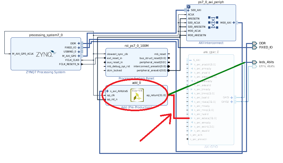
You don’t need the AXI GPIO block. You will connect your ap_return directly to LEDs. It looks like you used an int. This will be 32 bits, but you only need 4 bits for the LED. You should see a warning about this “32 bit is connected to a 4-bit, the upper bits are unconnected”, but the tools should automatically optimize this.You can use a “slice” and “concat” blocks to select a number of bits (wires) or to join bits into a wider signal.
You can use a smaller data type in C (e.g. char) but you will still have 4 bits unconnected. You can use custom data types in HLS (see “Data Types for Efficient Hardware” in the HLS user guide I linked to), but don’t worry about this for now.
The buttons are inputs, so you need to deal with them in a different way. You can’t connect them to ap_return.
You could add another input to your HLS c code.
You need ot make sure you don’t add this input to the AXI lite interface so that you generate an interface with wires that you can connect to the buttons.
ap_return is OK for this simple example, where you only have one output. When you have more than one output, you need to use pointers or references for your outputs.
Refer to the table in the HLS user guide I linked earlier for the default interfaces for different parameter types.
Cathal
I really appreciate this input.
I’ve managed to remove buttons entirely so I only have leds_4bits connected to the AXI GPIO block.
Furthermore I understand your 32bit / 4bit concern, and like you say, this is the least of my concerns as long as it only raises a warning and not an error. I can mask other bits in HLS code.
But, I cannot connect my output to leds_4bits… it just won’t connect. The leds_4bits only connects to one of those M00_AXI ports (which I don’t know what they are or at least how to convert my output to one of those)
You don’t need the AXI GPIO block at all. Remove it, and connect the output of your block (ap_return) directly to the LEDs.
To explain, the AXI GPIO block allows you to control GPIO from an AXI interface. i.e. from the Zynq PS, you can write a value to an address, and the AXI GPIO block will decode the address and pass on the value to the GPIO (or if the AXI transaction is a read, it will return the value from the wires).
Think about this block as doing the conversion from a memory-mapped transaction to the wires it eventually connects to.
In your case, you don’t need the memory mapped conversion as this is taken care of in your HLS block. You output a value on ap_return which is just wires, so you can connect this directly your LEDs.
Cathal
It won’t connect, ie Vivado says that no matching point found. I don’t know if I can force connect ap_return to Leds?
OK, the led port probably has “GPIO” type specified, so it expects the other “end” to connect to a GPIO bundle of signals. This would be a triple bundle of signals with a GPIO_i, _o and _t.
You could try to change the setting for the port, but I’d suggest an easier way is to delete the existing LED port, select the ap_return and type CTRL + T (or right click and find the “create new port” option). This will generate a new port that will be connected to the signal you have selected.
The existing lsds_4bits probably has pin constraints already set, so you may need to add pin constraints for this port manually.
For the PYNQ-Z2 you would need to create and add a new constraints file (.xdc) with the following:
##LEDs
set_property -dict { PACKAGE_PIN R14 IOSTANDARD LVCMOS33 } [get_ports { led[0] }];
set_property -dict { PACKAGE_PIN P14 IOSTANDARD LVCMOS33 } [get_ports { led[1] }];
set_property -dict { PACKAGE_PIN N16 IOSTANDARD LVCMOS33 } [get_ports { led[2] }];
set_property -dict { PACKAGE_PIN M14 IOSTANDARD LVCMOS33 } [get_ports { led[3] }];
Where led is your port name. You can rename the port to match the constraint or vice versa.
Let me know if any of this doesn’t make any sense.
Cathal
I think it makes sense, thank you!
So, I’ve freestyled through the options and generated a new port

And blocks look like this now
Regarding the XDC file, I have no idea what you are talking about.
- Where/when should this file be placed?
- I have a Z1, does it affect the pin numbers?
- How do you know all this? I mean, if I were to repeat all this, but output to IO’s instead, how to know what pin number to write in the xdc file?
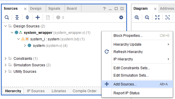
- if you go to the “Sources” panel, right click and find the “Add sources” option, then select add or create constraints. You can create the file here and it will be added to the project. You can then copy and paste the constraints.
-
The Z1/Z2 are the same. 
-
You get the pin information from the manufacturer of the board. It can be in a user guide, or other documentation, or provided in an XDC file.
You can find pin info for the PYNQ-Z1 here; download the full XDC, or check the userguide
PYNQ-Z1 - Digilent Reference
User guide: (see section 12 for the “basic” io and read the led pins off the image):
Cathal
You’re a hero! I managed to create the contraint file and copy pasted your input (yes, changed to LED_PORT in contraints file ;)).
Just a minor problem with my Pynq board now, I posted in Digilents forum: Pynq Z1: Is power regulator toast? - Digilent Microcontroller Boards - Digilent Forum

HOW???
So I got a new Pynq (we’ll see about warrant claim on the previous one).
I changed return type to 4 bit char using ap_uint to get rid of that warning that made me nervous:
#include “ap_int.h”
ap_uint<4> add(char a) {
#pragma HLS INTERFACE ap_ctrl_none port=return
#pragma HLS INTERFACE s_axilite port=a
return (ap_uint<4>) (a & 0xf);
}
Aaaand… IT’S WORKING, I can set the LED’s on off using the 4 bits.
THANK YOU.
Is there a way of repeating this exercise but output to IO’s instead of LED’s?
I.e. just use the “shield_dp0_dp13” module and connect it to my “scalar_add” block?
And also, create that constraints file thingy if I manage to find the correct constraints.
(I use the AXI_GPIO block just to magically get the shield_dp0_dp13 block, just like I did with leds, otherwise I wouldn’t know how to create it, lol)
Ok, I did try and now I can output to GPIO’s 0-13 using my own block design and overlay. I would say this exercise was a great success.
Thank you very much @cathalmccabe for all your support and guidance.