
So I’m working on a signal generator of sorts but this is early stages so it’s just a setup to divide a signal by a factor of 2 or 3 and I am trying to use HLS to accomplish this. I’ve connected a DDS compiler directly to the DAC and observed the output as a regular 3.7MHz sine output. I then used a block that divides by 2 and another block that divides by 3. The results and the block diagrams are attached below. The division is odd in that it also performs a frequency division, which doesn’t make too much sense as the division operation is supposed to be linear but the frequency division is very much non-linear.
I’m not sure if HLS is the appropriate platform for what I intend as perhaps straight verilog might actually give me what I want. In any case, I think it might have something to do with the clocking but I’m not sure where to start looking for the issue. I’ve also attached the block diagram for reference.
-
Block diagram

-
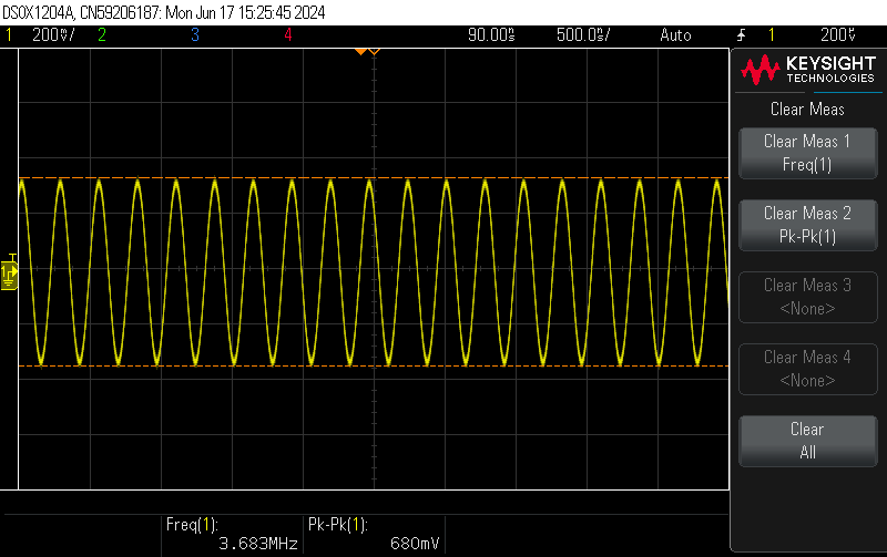
No division by 2
no div — Postimages -
Divsion by 2
div 2 — Postimages
From the above images, the signal goes deteriorating as the division factor increases. Not to mention the non-linear behaviour previously discussed. The RF data converter for the DAC is set to real->real and it gets a 16-bit alue from the DDS.
As always, any help or direction to material to assist me with this would be much appreciated.
