I’m using PYNQ 2.7.0 on the RFSoC 4x2 with the base overlay.
I’m trying to change the ADC decimation factor to a factor of 40x. The only modifications of the base overlay I’ve done are changing the decimation factor in Vivado for tile 224 (leaving 226 alone), which in turn changes the required AXI4-stream clock from default of 307.2MHz to 15.36MHz. Besides that, everything is the same.
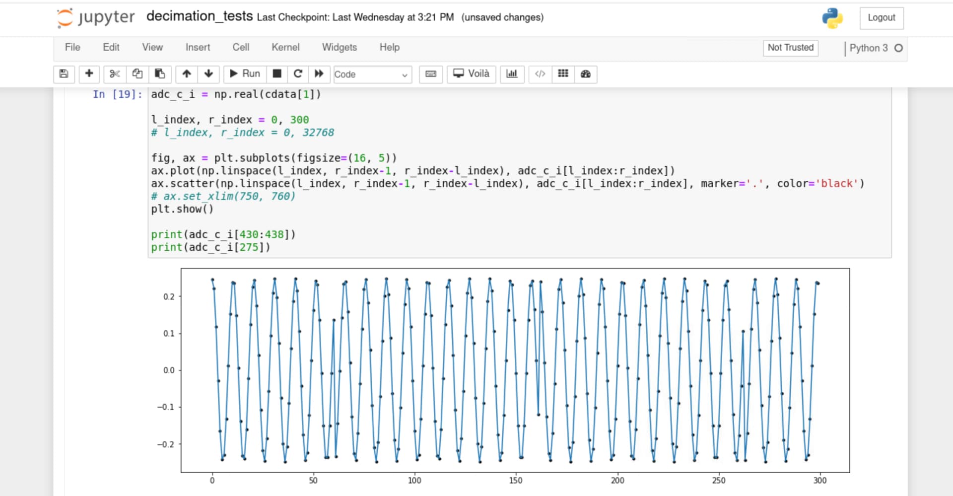
Using PYNQ, the data that comes out looks good except there is a change in phase/samples are skipped every 101 samples. My signal set up is an external RF generator set at 1497 MHz with the ADC mixer set to -1485MHz. I’m not sure what is causing this, as it doesn’t appear in the tile 226 data at the default 2x decimation factor. Since I didn’t change the samples/AXIS cycle, the packet generator should still be receiving the expected 16 bytes of data, and the clock converters should handle the new AXIS clock, so I think this issue may be on what PYNQ is expecting.
Does anyone have any ideas? Any help would be much appreciated. Thanks!
I had the same issue, and it was because I hadn’t actual changed the AXI stream input clock at the rfdc or anywhere else. I was modifying the RFSoC MTS bitstream at the time, and for that I had to modify the clock generated in the clock wizard in MTSClockwizard. If you’re working on a different design you’ll have to find the corresponding clock generator that feeds into the rfdc axis clock ports, and make sure that it’s actually getting the 15.36 MHz input that it’s expecting.
Hi, apologies for the delay as I was moving our lab. Yes, I did indeed not have the AXIS clock set right, but after changing to the correct clock I am getting the same error.
I am running the base overlay supplied for the RFSoC, so sX_axis_aclk is receiving clock from the DAC tiles (clk_dacX). In the rfdc clocking settings, the available outputs for the output speed didn’t get low enough to 15.36 MHz (due to the DAC sampling rate of 4.9152 GHz), so I changed decimation to 16x and changed the clk_dac0 in the rfdc to 38.4MHz, which is the required clock speed for ADC tile 224 (where I changed the decimation factors). When I run the code used to generate my original plots, I still get issues, but now the changes in phase are at a lower frequency. I assume that the required AXIS clock is still not being delivered but not too sure what to do from here. Any ideas? Regarding the base overlay, I think that the ADCs are getting the fabric clock from the DACs but not sure where in turn the DACs are getting their own fabric clock/AXIS clock?
I am going to try to plug everything into the ILA to troubleshoot…
Glad you were able to make some progress. My gut is telling me that the rest of the system clocks may have to adjusted as well to account for this change, as the AXI4-Stream clock converter in receiver/channel_ can only work with AXIS streams operating at certain frequencies as it works in integer clock ratios. I’m definitely not sure though, so let us know what you find from the ILA.
I figured it out – was running the new AXIS clock into the wrong input. I found on a Xilinx guide on ways to supply AXIS clock it said for an ADC tile you could run it into s0_axis_aclk; however the pin for ADC tile is m0_axis_aclk in the base overlay. So running adc0_clk into m0_axis_aclk was the solution. Thanks for the help!