AXI DMA puzzle (maybe)

DMA issue that might be due to software initialization

I think this is a PYNQ problem, not a Xilinx problem. What I have is a very simple design with the ZYNQ block, connected to 2 DMA blocks. One of the blocks reads from DDR and streams into an AXI fifo (so only the READ port is enabled), the other reads from the fifo and writes into DDR (so only the WRITE port is enabled). This is basically the same project as in the tutorial:

with a few minor changes, and updated using the RealDigital 4x2 gen 3 RFSoC and Vivado 2024.2.

In PYNQ, I load the project via Overlay(), and set up the base pointers to the two DMA engines and immediately print out the control and status registers. I’m looking at the documentation here:

and on page 27 it describes the control register bits and on page 29 the status register. On page 28 it says that bit 1 of the control register is reserved and will always be read as a 1.

What I find is that for the DMA that only reads from DDR, the control register comes up 0x0 and the status register also 0x0. Which is what I expect for status but I would have expected control to come up as 0x2.

For the DMA the takes data from the fifo (over AXIS stream) and writes into DDR, the status register comes up 0x0 as expected but the control register comes up 0x10003. Bit 1=1 which is what I expected, but bit0=1 which means DMA is running. And bit 16=1 which has something to do with interrupts, which I don’t enable (and don’t know HOW to enable!).

I asked chatgpt about this, and it agreed that 0x10003 was “wrong” and then said

"This almost certainly came from auto-generated init scripts or Python overlay code

Of course, it’s just a stupid computer program.

Anyway, I’m wondering if this has something to do with the fact that the DMA that has the WRITE port enabled is looking at a FIFO output, and maybe somehow it’s getting turned on when the FIFO AXI ready is asserted? Could it be something like that?

Does anyone have any advice?

Thanks!
Drew

Hmm, maybe it’s actually ok. Here’s what Claude.ai says (either it’s ok or Claude was just telling me what it thinks I wanted to hear!):

Looking at your AXI DMA control register value of 0x10003, this appears to be the expected default state for an AXI DMA after loading the bitstream. Let me break down what those bits mean:

Bit 0 (LSB = 1): This is the Run/Stop bit for the MM2S (Memory-to-Stream) channel. When set to 1, it indicates the MM2S channel is in the “run” state and ready to process descriptors. This is the normal default state after reset.

Bit 16 (= 1): This is the Run/Stop bit for the S2MM (Stream-to-Memory) channel. Similarly, when set to 1, it indicates the S2MM channel is in the “run” state and ready to process descriptors.

Why these bits are set by default:

  • The AXI DMA IP comes out of reset with both channels enabled and ready to accept descriptor chains
  • This is the normal “idle but ready” state - the DMA is not actively transferring data, but it’s prepared to start when you provide valid descriptors
  • The fact that there are no interrupts doesn’t affect these run/stop bits - they’re separate control mechanisms

What this means for your system:

  • Your DMA is properly configured and ready for operation
  • Both MM2S (DDR → AXI FIFO) and S2MM (AXI FIFO → DDR) paths are enabled
  • You can now start transfers by writing descriptor addresses to the appropriate tail pointer registers

This is completely normal behavior. The 0x10003 value indicates your AXI DMA is in the correct operational state after bitstream loading.

I asked Claude.ai for the documentation that says that the initialization should be with 0x10003 in the control register, and it apologized and said it could not find such documentation.

I should have been clearer in describing what I see. So if I have 1 DMA engine with both MM2S and SS2M enabled, then after overlay each will report 0x10003 for the control register - both are in the RUN mode. This is what I want to understand, and find some documentation that describes what is happening when.

Hi @drewphysics,

I am trying to understand what is the issue. Are you having a problem when running the data movement? Or would you like to understand the registers?

I suggest you use the PYNQ register_map feature, so it is easier to decode the registers.

You are also looking and old version of the documentation. The latest one is https://docs.amd.com/r/en-US/pg021_axi_dma/Introduction

Hi Marioruiz, thanks for your reply and link.

I guess what I’m really curious is the following:

  1. in my python code, I get the base pointer from the Overlay() function. My AXI DMA engine is named “AXI_DMA”. so when I issue the command dma = base.AXI_DMA and then read the control registers, both MM2S and S2MM come up as 0x10003. Bit0 = 1 means it is in the running state. I think this is because the DMA engine is now waiting for descriptors, so it’s “RUNNING”. But I don’t understand why bit 16 is asserted. The documentation says that this field is ignored if I’m in direct DMA mode (not scatter-gather) so I guess it’s benign but I’m trying to understand
  2. the other thing I’m trying to understand (just to understand) is what are the states of bit 0 of the control register, and bits 0 and 1 of the status register for both the DMA read from DDR into the stream and the DMA write into DDR from the stream (which in my case is an AXI FIFO).
  3. what are the conditions for doing DMA reading and writing, in terms of whether the DMA engine is IDLE or not. I ask this because I have the following situation: I allocate 100 words of DDR for the send channel, and 10 for receive. I do a send.transfer of the buffer that has 100 words, then I do a receive.transfer of the other buffer that has 10 words. I don’t specify the size of the transfer, because I’m assuming that it just transfers all of it. So the code looks like this:
# setup dma
dma=base.AXI_DMA    #AXI_DMA is a dictionary entry
dma_send = dma.sendchannel
dma_receive = dma.recvchannel
# allocate buffers in DDR
buffer_in = allocate(shape=100,), dtype=np.uint32)
buffer_out = allocate(shape=10,), dtype=np.uint32)
# check MM2S and S2MM control and status registers:
--> both control registers at 0x10003 and both status registers at 0
# execute dma write from buffer_in into fifo
dma_send.transfer(buffer_in)
# check control and status registers:
MM2S ctrl=0x10003  stat=0x1002 (IDLE)
S2MM same as MM2S
# transfer from fifo to DDR
dma_receive.transfer(buffer_out)
# check control and status registers:
MM2S ctrl=0x10002 (NOT running)   stat=0x1001 (HALTED)
S2MM ctrl=0x10002 (NOT running)   stat=0x5011 (DMAIntErr and Halted)

So it looks like DMA had an error?

If at this point I were to try another transfer of data into the FIFO, I get an error from dma.py:
“DMA channel not started”. I want to understand what I am doing wrong!

And my apologies for the long reply, thanks so much for any help.

Drew

Hi Drew,

The DMA user guide should give you the information to the DMA registers.

As per your code. I would say that the first transaction never finished. This is likely why you get the halt bit and the `DMA channel not started`.

Without seeing the block design, it is hard to say what could be wrong.

Mario

Thanks for your comments! I checked with a .wait() and it came back finished immediately. This is as expected since it was only 100 words of 4 bytes each.

Here is the project. the AXI_DMA module is configured to not have scatter-gather enabled, and the buffer length register is set to 26 but otherwise nothing else is changed from defaults. On the ZYNQ block, as you can see I’ve enabled the 2 AXI HP0 FPD and HP1 FPD ports and left the data width at 128. For the FIFO, the depth is set to 512, everything else is default but I did enable read and write data lengths.

I took a closer look at what’s happening. Questions are in bold italics.

After the dma is setup, before transfers:

MM2S SS2M
Control 0x10003 0x10003
Status 0x0 0x0

This looks normal except for bit 16 of the control register, but the documentation says it’s ignored. So I guess I don’t have to worry about it?

Execute DMA transfer on MM2S, 100 words

MM2S SS2M
Control 0x10003 0x10003
Status 0x1002 0x0

The MM2S status register has bit0=0 meaning the channel is RUNNING, bit1=1 meaning the channel is IDLE, and bit 12=1 meaning an interrupt has been generated on completion of the transfer. Maybe this is normal and just indicates the transfer is complete, but the documentation (which might have a few typos) says that this bit is set if the control register bit12 is set that enables it to be set on transfer completion. Since that control bit 12 is NOT set, why is this bit in the status register set?

The SS2M channel control and status registers haven’t changed, which is expected since I only executed MM2S.

Execute DMA S2MM, 10 words

MM2S SS2M
Control 0x10002 0x10002
Status 0x1001 0x5011

The MM2S control register changes from 0x10003 to 0x10002 meaning that the channel is not running (STOP state). There will still be data in the fifo (write 100 words in, read 10 out). So why would the MM2S control register change after a S2MM transfer?

The S2MM register also changes. 0x5011 has bit0=1 which means the channel is HALTED, and bit1=0 so the channel is in the NOT IDLE state. Also, bits 12 and 14 are asserted. Bit 12 is asserted if there was an interrupt generated on transfer completion, but the documentation says that this will happen if bit 12 in the control register is asserted to enable it. And it is not. So why is bit 12 asserted in the status register if bit12=0 in the control register? Also, bit 14 is asserted which the documentation says means there was an interrupt error. What does that mean?

So as you can see I’m a bit confused as to what I am seeing, given what I expect from putting this simple project together. Thanks so much for any comments and help!

Drew

Hi @drewphysics,

I do not have a great answers to your questions. I may suggest you post them in the Xilinx forums.

Another suggestion will be to use independent DMAs for each channel.

Mario

Thanks, separate DMA engines is a good idea. I tried it and I get the same errors when reading the FIFO.

I then made the buffers the same size, doing a DMA write 100 words into the FIFO, and then DMA read 100 words back into DDR. When I then look at the control and status registers, I see no errors.

So it’s something to do with the FIFO I think. Any ideas would be great! I will post this to the Xilinx forum and report back if I get any responses.

Drew

It could be because the 10 word transaction does not have TLAST.

You can try to add an IP (AXI4-Stream Subset Converter) to assert TLAST after 10 transactions.

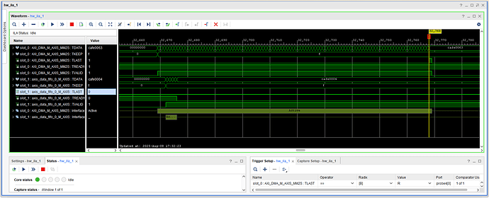
I built a project with the System ILA.

In the following, the top 5 signals are from the MM2S channel that writes into the AXI FIFO, and the next 5 are from the S2MM channel that reads from the FIFO.

This first picture is from sending 100 words into the FIFO. Each word has 0xcafe in the upper 16 bits and then a counter in the lower 16. You can see that it starts with 0 and ends with 0xcafe0063, which means it sent 100 words. The trigger is on TLAST and it comes up for 1 clock tick.

This next picture is triggering on TLAST on the S2MM channel, where I read 100 words from the FIFO. You can see the last 0xcafe0063, and TLAST posedge. Curious why TLAST never goes back down. I can only assume from this that the system uses the FIFO empty flag for TLAST. Could that be true?

I then did a test where I first reset everything (redownload), then wrote 100 words into the FIFO, then read back 10. The first curious thing is that the data starts at 0xcafe0004. Must be another FIFO somewhere? Anyway, I only asked for 10 words but it kept going until it got to 0xcafe004d. 0x4d is decimal 77, so on the 78th word it stops transmitting, and TLAST is never asserted. Hence the error.

Here is my python code:

from pynq import Overlay, allocate, MMIO
import lumpy as np

base = Overlay("test_dma.bit")
base.ip_dict  # returns AXI_DMA among other AXI modules
dma = base.AXI_DMA
dma_send = dma.sendchannel
dma.receive = dma.recvchannel
send_size = 100
buffer_send = allocate(shape=(send_size,), dtype=np.uint32)
rec_size = 10
buffer_rec = allocate(shape=(rec_size,), dtype-np.uint32)
for i in range(send_size):
      buffer_send[I] = 0xcafe + I

# here is the MM2S transactions
dma_send.transfer(buffer_send,0,4*send_size)

# here is the S2MM transactions, in another cell
dma_receive.transfer(buffer_rec,0,4*rec_size)

Thanks so much for all help!

Drew

If TVALID is de-asserted, any other signal has no meaning.

Must be another FIFO somewhere?

The DMA consumes 4 words without being started, it has a small FIFO.

At the end of the day, the issue is that the DMA expects a TLAST with the last beat, when you request 10 words, this does not happen hence the errors you see. You will need to add hardware to handle the TLAST properly.