
Solved
Fixed Flow Steps
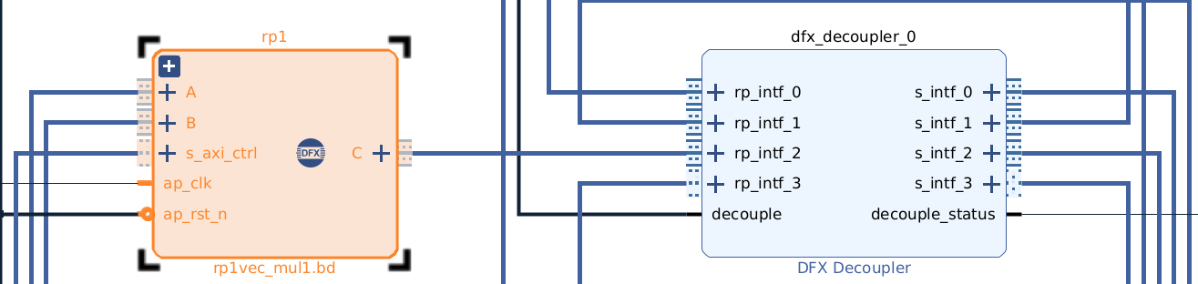
The static region includes:
- Three AXI DMAs (two input DMAs for A and B, one output DMA for C)
- AXI GPIO for decoupling the reconfigurable region
- One Reconfigurable Partition (RP1)
Two HLS-based accelerators share the same reconfigurable region:
vec_add— performs element-wise additionvec_mul— performs element-wise multiplication
1. Make sure all RP interfaces are correctly decoupled
Before loading any partial bitstream:
gpio.write(0, 1)  # Decouple ON before PR
# ... download partial bitstream ...
gpio.write(0, 0)  # Decouple OFF after PR
2. Enable reset and snapping mode in XDC
In your .xdc file, ensure the following properties are applied to the RP pblock:
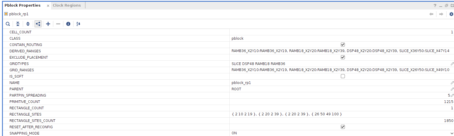
set_property RESET_AFTER_RECONFIG true [get_pblocks pblock_rp1]
set_property SNAPPING_MODE ON [get_pblocks pblock_rp1]
This ensures the RP resets properly and aligns with static region boundaries.
Final Python Script
from pynq import Overlay, allocate
import numpy as np
import time

# ==========================================================
# 1. Load Static Region
# ==========================================================
overlay = Overlay("static_f.bit")
print("Static overlay loaded.")

gpio = overlay.axi_gpio_0

# ==========================================================
# 2. PARTIAL RECONFIGURATION: Load vec_add RM
# ==========================================================
print("\n--- Loading vec_add Partial Bitstream ---")
gpio.write(0, 1)  # Decouple ON
time.sleep(0.5)

overlay.rp1.download('vec_add2.bit')
time.sleep(0.5)
gpio.write(0, 0)  # Decouple OFF
time.sleep(0.2)
print("vec_add RM loaded successfully.\n")

# ==========================================================
# 3. DMA and IP Setup
# ==========================================================
input_a = overlay.axi_dma_0
input_b = overlay.axi_dma_1
output_c = overlay.axi_dma_2
vec_add = overlay.rp1.vec_add_0

def print_dma_status(dma, direction):
    """ direction: 0 = read channel (MM2S), 1 = write channel (S2MM) """
    offset = 0 if direction == 0 else 0x30
    kind = "Read" if direction == 0 else "Write"
    print(f"{kind} Channel:")
    print(f"  Control: {hex(dma.read(0x0 + offset))}")
    print(f"  Status : {hex(dma.read(0x4 + offset))}\n")

print_dma_status(input_a, 0)
print_dma_status(input_b, 0)
print_dma_status(output_c, 1)

# ==========================================================
# 4. Prepare Buffers and Data
# ==========================================================
N = 32
input_buffer_a = allocate(shape=(N,), dtype=np.uint32)
input_buffer_b = allocate(shape=(N,), dtype=np.uint32)
output_buffer_c = allocate(shape=(N,), dtype=np.uint32)

for i in range(N):
    input_buffer_a[i] = i + 1
    input_buffer_b[i] = (i + 1) * 10

print("Input A:", input_buffer_a)
print("Input B:", input_buffer_b)

# ==========================================================
# 5. Run vec_add IP
# ==========================================================
vec_add.write(0x10, N)      # LEN register
vec_add.write(0x0, 0x1)     # Start IP

input_a.sendchannel.transfer(input_buffer_a)
input_b.sendchannel.transfer(input_buffer_b)
output_c.recvchannel.transfer(output_buffer_c)

input_a.sendchannel.wait()
input_b.sendchannel.wait()
output_c.recvchannel.wait()

print("DMA Transfers Completed.\n")

print("Output C:", output_buffer_c)
expected_add = input_buffer_a + input_buffer_b
if np.array_equal(output_buffer_c, expected_add):
    print("vec_add output is correct!\n")
else:
    print("vec_add output mismatch!")
    print("Expected:", expected_add)
    print("Got     :", output_buffer_c)

# ==========================================================
# 6. PARTIAL RECONFIGURATION: Load vec_mul RM
# ==========================================================
print("\n--- Loading vec_mul Partial Bitstream ---")
gpio.write(0, 1)  # Decouple ON
time.sleep(0.5)

overlay.rp1.download('vec_mul1.bit')
time.sleep(0.5)
gpio.write(0, 0)  # Decouple OFF
time.sleep(0.2)
print("vec_mul RM loaded successfully.\n")

# ==========================================================
# 7. Reconnect IP and Run vec_mul
# ==========================================================
vec_mul = overlay.rp1.vec_mul_0  # new HLS block after PR

# Reset output buffer
output_buffer_c[:] = 0

vec_mul.write(0x10, N)      # LEN register
vec_mul.write(0x0, 0x1)     # Start IP

input_a.sendchannel.transfer(input_buffer_a)
input_b.sendchannel.transfer(input_buffer_b)
output_c.recvchannel.transfer(output_buffer_c)

input_a.sendchannel.wait()
input_b.sendchannel.wait()
output_c.recvchannel.wait()

print("DMA Transfers Completed (vec_mul).\n")

print("Output C:", output_buffer_c)
expected_mul = input_buffer_a * input_buffer_b
if np.array_equal(output_buffer_c, expected_mul):
    print("vec_mul output is correct!\n")
else:
    print("vec_mul output mismatch!")
    print("Expected:", expected_mul)
    print("Got     :", output_buffer_c)

# ==========================================================
# 8. Clean Up
# ==========================================================
input_buffer_a.freebuffer()
input_buffer_b.freebuffer()
output_buffer_c.freebuffer()

print("All done. Both PR modules (vec_add & vec_mul) tested successfully.")
 Example Console Output
Static overlay loaded.

--- Loading vec_add Partial Bitstream ---
vec_add RM loaded successfully.

Read Channel:
  Control: 0x10003
  Status : 0x0

Read Channel:
  Control: 0x10003
  Status : 0x0

Write Channel:
  Control: 0x10003
  Status : 0x0

Input A: [ 1  2  3 ... 31 32]
Input B: [ 10  20  30 ... 310 320]
DMA Transfers Completed.

Output C: [ 11  22  33 ... 341 352]
vec_add output is correct!

--- Loading vec_mul Partial Bitstream ---
vec_mul RM loaded successfully.

DMA Transfers Completed (vec_mul).

Output C: [   10    40    90 ... 9610 10240]
vec_mul output is correct!

All done. Both PR modules (vec_add & vec_mul) tested successfully.
 References
- PYNQ DMA Tutorial (Part 1)
- YouTube: PYNQ DPR Setup (Series)
- YouTube: PYNQ DMA Walkthrough
- DMA — Python productivity for Zynq (Pynq)
- AMD Technical Information Portal
Final Verification:
Both vec_add and vec_mul reconfigurable modules successfully loaded, executed, and validated via DMA transfers under the same static design.